


Product description:
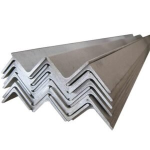
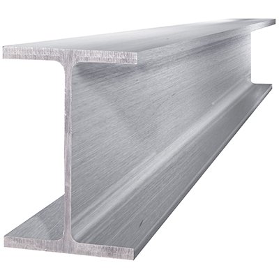
A beam is a structural element that supports a building or structure. It can be either primary support or secondary support and is generally used to bear a load from some other member, such as a foundation or the outer walls.
Beams are classified by their shapes (I-beams, L-beams, box beams) and sizes (2×4, 2×6). They’re also classified by their material and how they’re attached to the structure of the building. Beams are generally made from wood, steel or concrete. In addition to these materials, some beams can be made with bamboo or balsa wood as well.
Beams are often used when constructing buildings because they allow for easy installation of wiring and piping without having to worry about overworking any one part of the building too much.
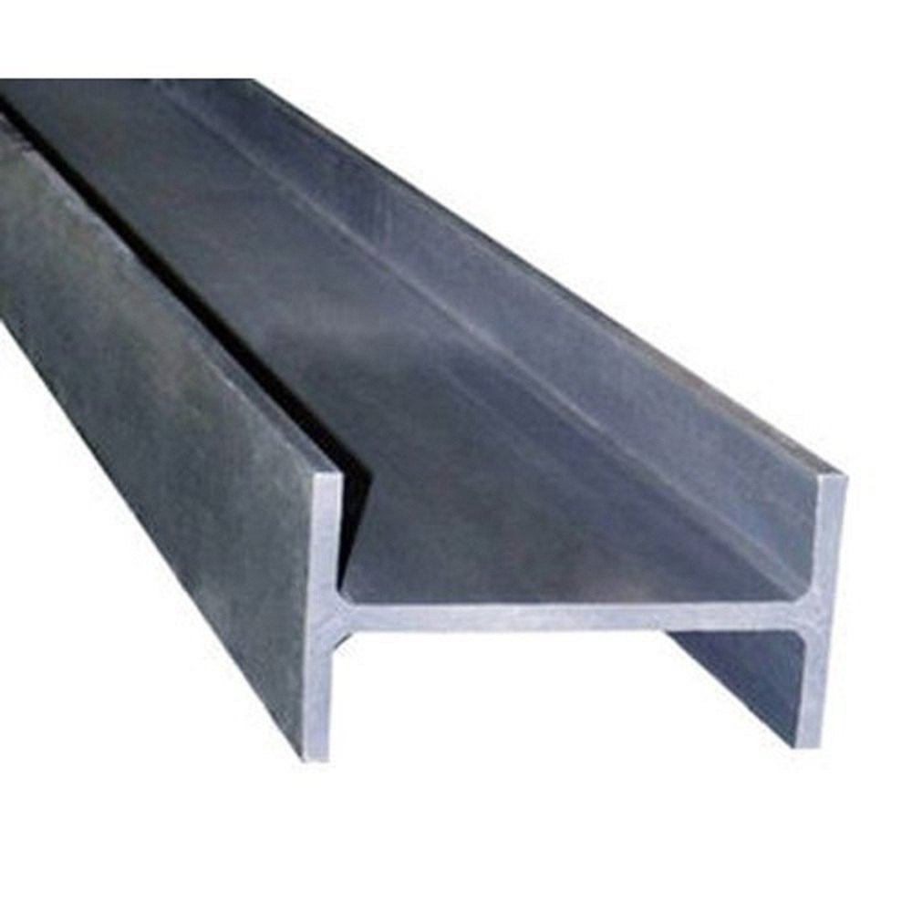
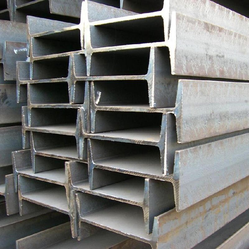
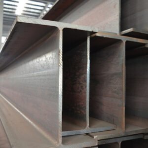
The inner and outer sides of the flange of H-shaped steel are parallel or nearly parallel, and the end of the flange is at right angles, so it is named parallel flange I-beam. The web thickness of H-shaped steel is smaller than that of ordinary I-beam with the same height as the web, and the flange width is larger than that of ordinary I-beam with the same height as the web, so it is also called wide edge I-beam. Determined by the shape, the section modulus, inertia moment and corresponding strength of H-beam are obviously better than those of ordinary I-beam with the same single weight. When used in metal structures with different requirements, it shows its superior performance in terms of bending moment, pressure load and eccentric load. It can greatly improve the bearing capacity and save 10% ~ 40% of metal compared with ordinary I-beam. H-shaped steel has wide flange, thin web, many specifications and flexible use. It can save 15% ~ 20% of metal when used in various truss structures. Because the inner and outer sides of the flange are parallel and the edge ends are at right angles, it is convenient to assemble and assemble various components, which can save about 25% of the welding and riveting workload, greatly accelerate the construction speed of the project and shorten the construction period.
| Material | A36、St37、St52,16Mn,S235J0、S235J2,S235JR,S355JR,S355,S355J0SS440,SM400A,SM400BQ195,Q235B,Q355B, |
| Production Range | A572,GR50,GR60,SS540H100*100-H400*400H150*75 -H900*300 |
| Standard | ASTM A36;ASTM A6(W);ASTM A6(S);JIS 3192;JIS 3136;EN10034;EN10163;EN10025-2;AS/NZS3679.1; |
| Length | 6m, 9m, 12m or as customer requirement |
| Technology | Hot rolled,welded |
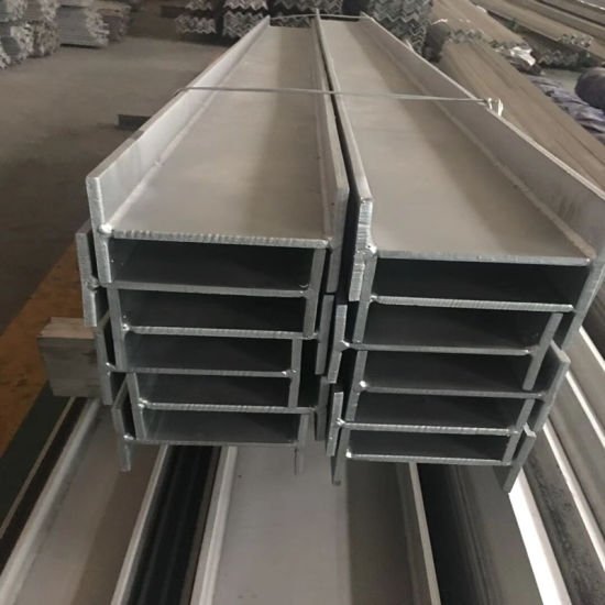
| Surface | Galvanized, paint;or as your request |
| Supply ability | 2000Ton/day |
| Business type | Manufacturer |
| Certification: | ISO, SGS,BV |
| Application | widely used in building structure and engineering construction, such as room beam,ship beam, industrial furnace, etc. |
| Loading port | any port in China |
| Packing | standard export packing or as your requirement |
| Payment Terms | T/T, L/C at sight,West Union,D/P,D/A,Paypal |
| Brand name |
WISDOM STEEL |
|||
| Products name | hot rolled H-beam hot dipped galvanized structural steel h beam Welded H steel beam section profile | |||
| Material | Q235B, Q345B, Q255, Q275, SS400, A36, SM400A, St37-2, SA283Gr, S235JR, S235J0, S235J2 | |||
| Standard |
ASTM, AISI, JIS, GB, DIN, EN |
|||
| length |
6M, 12M, or As required |
|||
| price terms | FOB, CRF, CIF, EXW all acceptable | |||
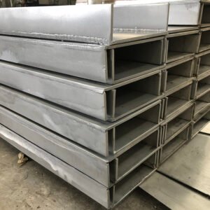
| Packing | Carbon steel is bare packaging; Other material is standard export packing (inside: water proof paper, outside:steel covered with strips and pallets). |
|||
| Country of Origin | CHINA | |||
| European standard I-beam theoretical weight specification table | |||||
| Specification | height | width | web thickness | wing thickness | theoretical weight |
| IPE80 | 80 | 46 | 3.8 | 5.2 | 6 |
| IPE100 | 100 | 55 | 4.1 | 5.7 | 8.1 |
| IPE120 | 120 | 64 | 4.4 | 6.3 | 10.4 |
| IPE140 | 140 | 73 | 4.7 | 6.9 | 12.9 |
| IPE160 | 160 | 82 | 5 | 7.4 | 15.8 |
| IPE180 | 180 | 91 | 5.3 | 8 | 18.8 |
| IPE200 | 200 | 100 | 5.6 | 8.5 | 22.4 |
| IPE220 | 220 | 110 | 5.9 | 9.2 | 26.2 |
| IPE240 | 240 | 120 | 6.2 | 9.8 | 30.7 |
| IPE270 | 270 | 135 | 6.6 | 10.2 | 36.1 |
| IPE300 | 300 | 150 | 7.1 | 10.7 | 42.2 |
| IPE330 | 330 | 160 | 7.5 | 11.5 | 49.1 |
| IPE360 | 360 | 170 | 8 | 12.7 | 57.1 |
| IPE400 | 400 | 180 | 8.6 | 13.5 | 66.3 |
| IPE450 | 450 | 190 | 9.4 | 14.6 | 77.6 |
| IPE500 | 500 | 200 | 10.2 | 16 | 90.7 |
| IPE550 | 550 | 210 | 11.1 | 17.2 | 106 |
| IPE600 | 600 | 220 | 12 | 19 | 122 |
H Steam
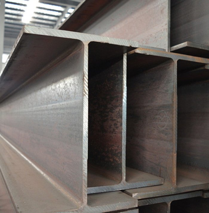
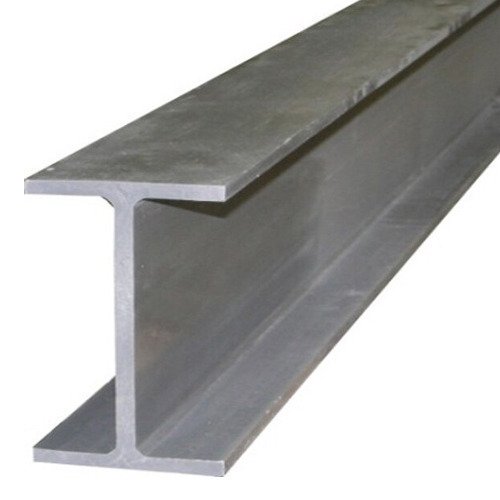
H-section steel is a kind of economical section and high-efficiency section with more optimized cross-sectional area distribution and more reasonable strength-to-weight ratio. It is named because its section is the same as the English letter “H”. Since the various parts of the H-shaped steel are arranged at right angles, the H-shaped steel has the advantages of strong bending resistance, simple construction, cost saving and light structure in all directions.
HE-B steel beam, also called H-beam. The H-beam is square with equal height and width.
The construction provides the beam with great strength and rigidity. The form of the beam prevents bending of the transverse parts.
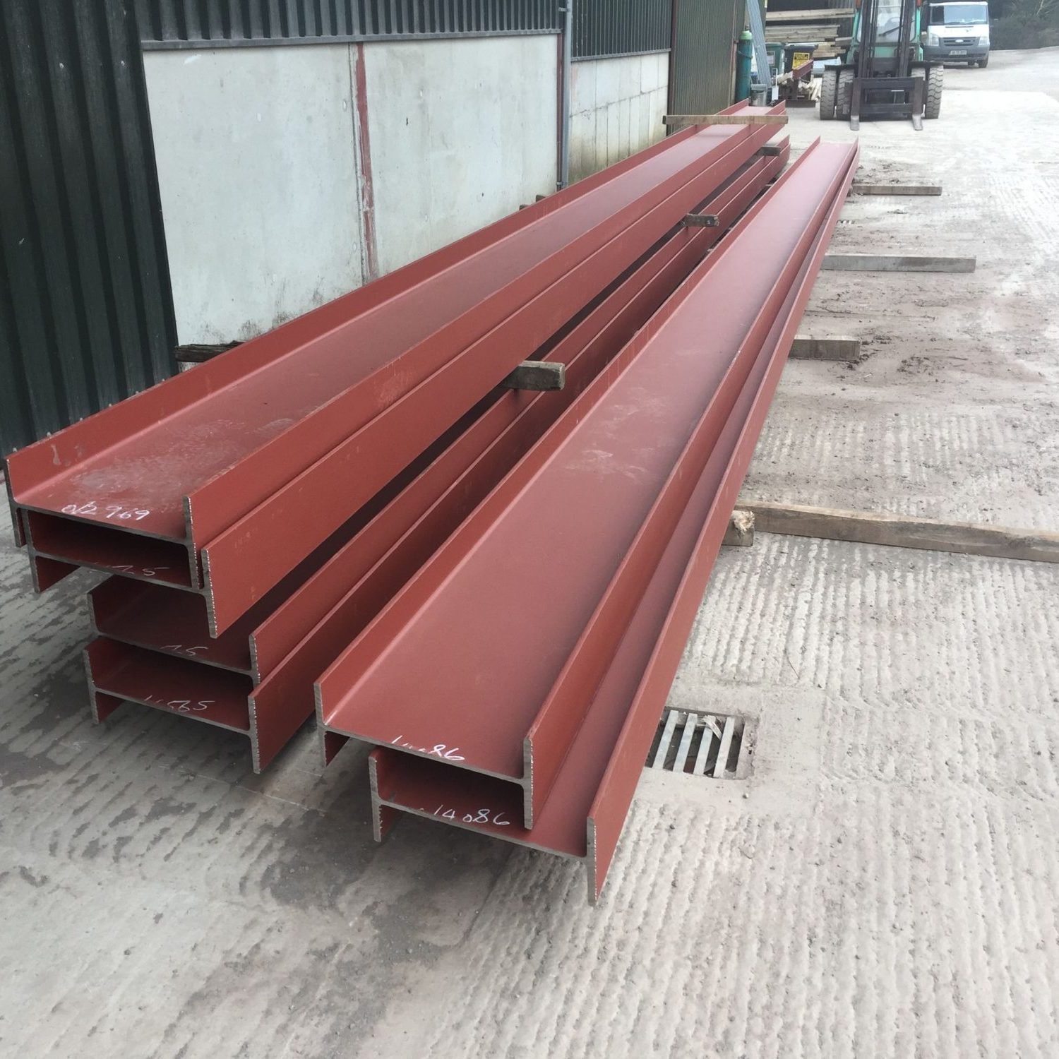
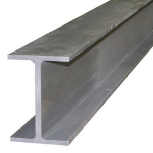
A steal beam is suitable for both indoor and outdoor use. However, it will rust over time, when it is exposed to the humidity of the air. Therefore, it rusts faster outdoor. If you would like to encourage the corrosion process, water can be added.
The steel H-steel beam can be used for enforcement of tiers of beams, poles, a bearer over a door or window, etc.
.jpg")
.jpg")
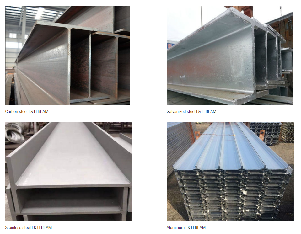
- Pipe Type:Structural H Beam,H Beam ,H section,Carbon Steel H-beam,Stainless Steel H-beam,
Galvanized H Beam,Aluminum H Beam,Alloy H Beam,Wide Flange Beam,High-Spec H-Beams,Patterned H-Beams
Size:100*50-700*300mm
Web Thickness:5-16mm
Web Width:50–300mm
Flange Thickness:4.5-23mm
Flange Width:50-400mm
Length:1-12m or as customer request
Standard:AISI,ASTM,DIN,JIS,GB ,JIS,SUS,EN,BS ISO.etc
Shape:H Channel/I Channel
Technique:Hot rolled/Cold Rolled/Galvanized
Edge:Mill Edge/ Silt Edge
Surface Treatment:Hot Dip Galvanized, Painting or Black.
Application:Construction,Decoration,Ship,Medical Equipment,Machinery,Mechanical&manufacture,Steel structure,Shipbuilding,Bridging, Automobile chassis
Steel Grade:
1015,1020,1035,1045,1055,1060,1213,1140,1215,9255,9262,1039,1025,1335,1330,1050,1095,4520,2515,3135,3415,3310,9840,8620,8740,4340,5015,5132,5140,5115,5155,4130,4137,4135,4140,
4142,6150,Ck10,Ck15,Ck22,Ck25,Ck30,Ck35,Ck40,Ck45,Ck50, 30Mn4,40Mn4 12Cr1MoV Cr5Mo
15CrMo 30CrMo 40CrMo 20SiMn 12Cr1MoVG 20CrNiMo 15CrMoG A3642CrMo 40CrNiMoA 50CrV
Stainless steel H-beam:
Length:1-12m or as customer’s request
height:100-1000mm
Width:100-407mm
Thickness:4.0mm-35mm
Tolerance:±0.05mm
Standard:AISI,ASTM,DIN,JIS,GB ,JIS,SUS,EN,etc
Technique:Hot rolled / cold rolled
Surface Treatment:No.1/No.3/No.4/HL/1D/8K
Material:201, 202, 301, 302, 303, 304, 304L, 304H, 310S, 316, 316L, 317L, 321,310S,309S, 410, 410S,420, 430, 431, 440A,904L
Application:Mechanical&manufacture,Steel structure,Shipbuilding,Bridging, Automobile chassisCarbon Steel H-beam:
Height:100-900mm
Width:50-400mm
Web thickness:5-30mm
Flange thickness:7-40mm
Standard:ASTM,AISI,JIS,DIN,EN,BS
Processing Type:Cutting, bending,stamping,welding,cnc machining
Cutting Type :Laser cutting;water-jet cutting;flame cutting
Surface Treatment:1),Bared2),Black painted (varnish coating)3),Galvanized4),With oiled-covered
Application:Construction,Decoration,Ship,Medical Equipment,Machinery,etc
Technique:Hot Rolled Edge:Mill Edge/ Silt Edge
Grade:1015,1020,1035,1045,1055,1060,1213,1140,1215,9255,9262,1039,1025,1335,1330,1050,1095,4520,2515,3135,3415,3310,9840,8620,8740,4340,5015,5132,5140,5115,5155,4130,4137,4135,4140,
4142,6150,Ck10,Ck15,Ck22,Ck25,Ck30,Ck35,Ck40,Ck45,Ck50, 30Mn4,40Mn4 12Cr1MoV Cr5Mo
15CrMo 30CrMo 40CrMo 20SiMn 12Cr1MoVG 20CrNiMo 15CrMoG A3642CrMo 40CrNiMoA 50CrV

Sepcification
-
Wide Flange Series

Classification
(Height × Flange width)Standard cross-section
dimensions (mm)Cross-sectional
area(cm3)Unit mass
(kg/m)H×B t1 t2 r 100×100 *100×100 6
8
8
21.59 16.9 125×125 125×125 6.5
9
8
30.00 23.6 150×150 150×150 7
10
8
39.65 31.1 175×175 175×175 7.5
11
13
51.43 40.4 200×200 200×200
*200×2048
1212
1213
1363.53
71.5349.9
56.2250×250 *244×252
250×250
*250×25511
9
1411
14
1413
13
1381.31
91.43
103.963.8
71.8
81.6300×300 *294×302
300×300
*300×30512
10
1512
15
1513
13
13106.3
118.5
133.483.4
93.0
105.0350×350 *344×348
*344×354
350×35010
16
1216
16
1913
13
13144.0
164.6
171.9113.0
129.0
135.0400×400 400×400 13
21
22
218.7 172.0 Classification
(Height × Flange width)Reference Second moment
of area(cm4)Radius of gyration
of area(cm)Section
modulus(cm3)lx ly ix iy zx zy 100×100 378 134 4.18 2.49 75.6 26.7 125×125 839 293 5.29 3.13 134.0 46.9 150×150 1,620 563 6.40 3.77 216.0 75.1 175×175 2,900 984 7.50 4.37 331.0 112.0 200×200 4,720
4,9801,600
1,7008.62
8.355.02
4.88472.0
498.0160.0
167.0250×250 8,700
10,700
11,4002,940
3,650
3,88010.30
10.80
10.506.01
6.32
6.11713.0
860.0
912.0233.0
292.0
304.0300×300 16,600
20,200
21,3005,510
6,750
7,10012.50
13.10
12.607.20
7.55
7.301,130.0
1,350.0
1,420.0365.0
450.0
466.0350×350 32,800
34,900
39,80011,200
11,800
13,60015.10
14.60
15.208.84
8.48
8.891,910.0
2,030.0
2,280.0646.0
669.0
776.0400×400 66,600 22,400 17.50 10.10 3,330.0 1,120.0 Medium Flange Series

Classification
(Height × Flange width)Standard cross-section
dimensions(mm)Cross-sectional
area(cm3)Unit mass
(kg/m)H×B t1 t2 r 200×150 194×150 6
9
8
38.11 29.9 250×175 244×175 7
11
13
55.49 43.6 300×200 294×200 8
12
13
71.05 55.8 350×250 340×250 9
14
13
99.53 78.1 400×300 390×300 10
16
13
133.30 105 450×300 440×300 11
18
13
153.90 121 500×300 482×300
488×30011
1115
1813
13141.2
159.2111
125600×300 582×300
588×300
594×30212
12
1417
20
2313
13
13169.20
187.20
217.10133
147
170700×300 692×300
700×30013
1320
2418
18207.50
231.50163
182800×300 792×300
800×30014
1422
2618
18239.50
263.50188
207900×300 *890×299
900×300
*912×30215
16
1823
28
3418
18
18266.90
305.80
360.10210
240
283Classification
(Height × Flange width)Reference Second moment
of area(cm4)Radius of gyration
of area(cm)Section
modulus(cm3)lx ly ix iy zx zy 200×150 2,630 507 8.30 3.65 271 67.6 250×175 6,040 984 10.40 4.21 495 112 300×200 11,100 1,600 12.50 4.75 756 160 350×250 21,200 3,650 14.60 6.05 1,250 292 400×300 37,900 7,200 16.90 7.35 1,940 480 450×300 54,700 8,110 18.90 7.26 2,490 540 500×300 58,300
68,9006,760
8,11020.30
20.806.92
7.142,420
2,820450
540600×300 98,900
114,000
134,0007,660
9,010
10,60024.20
24.70
24.806.73
6.94
6.983,400
3,890
4,500511
601
700700×300 168,000
197,0009,020
10,80028.50
29.206.59
6.834,870
5,640601
721800×300 248,000
286,0009,920
11,70032.20
33.006.44
6.676,270
7,160661
781900×300 339,000
404,000
491,00010,300
12,600
15,70035.60
36.40
36.906.20
6.43
6.597,610
8,990
10,800687
842
1.040Narrow Flange Series
Classification
(Height × Flange width)Standard cross-section
dimensions(mm)Cross-sectional
area(cm3)Unit mass
(kg/m)H×B t1 t2 r 200×100 *198×99
200×1004.5
5.57
88
822.69
26.6717.8
20.9250×125 248×124
250×1255
68
98
831.99
36.9725.1
29.0300×150 298×149
300×1505.5
6.58
913
1340.80
46.7832.0
36.7350×175 346×174
350×1756
79
1113
1352.45
62.9141.2
49.4400×200 396×199
400×2007
811
1313
1371.41
83.3756.1
65.4450×200 446×199
450×2008
912
1413
1382.97
95.4365.1
74.9500×200 496×199
500×200
*506×2019
10
1114
16
1913
13
1399.29
112.30
129.3077.9
88.2
102.0600×200 596×199
600×200
*606×20110
11
1215
17
2013
13
13117.80
131.70
149.8092.5
103.0
118.0Classification
(Height × Flange width)Reference Second moment
of area(cm4)Radius of gyration
of area(cm)Section
modulus(cm3)lx ly ix iy zx zy 200×100 1,540
1,810113
1348.25
8.232.24
2.24156
18122.9
26.7250×125 3,450
3,960255
29410.40
10.402.82
2.82278
31741.1
47.0300×150 6,320
7,210442
50812.40
12.403.29
3.29424
48159.3
67.7350×175 11,000
13,500791
98414.50
14.603.88
3.96638
77191.0
112.0400×200 19,800
23,5001,450
1,74016.60
16.804.50
4.56999
1.170145.0
174.0450×200 28,100
32,9001,580
1,87018.40
18.604.36
4.431,260
1,460159.0
187.0500×200 40,800
46,800
55,5001,840
2,140
2,58020.30
20.40
20.704.31
4.36
4.461,650
1,870
2,190185.0
214.0
256.0600×200 66,600
75,600
88,3001,980
2,270
2,72023.80
24.00
24.304.10
4.16
4.262,240
2,520
2,910199.0
227.0
270.0High-Spec H-Beams
Standard Type code Chemical composition Unit:(%) Unit:(%) Spec code C
(max.)Si
(max.)Mn P
(max.)S
(max.)Cu
(max.)Cr*6
(max.)Sn
(max.)Ceq Pcm JIS G 3101 SS400
–
–
–
0.050
0.050
–
–
–
–
–
YHS-SS400
0.20
0.35
0.80 or lower
0.030
0.015
0.40
0.25
0.040
0.36
or lower–
JIS G 3136 SN400B
0.20
0.35
0.60 – 1.40
0.030
0.015
–
–
–
0.36
or lower(0.26 or lower) *4
YHS-SN400B
0.20
0.35
0.60 – 1.40
0.030
0.015
0.40
0.25
0.040
0.36
or lower0.26 or lower
JIS G 3106 SM490A
0.20
0.55
1.65 or lower
0.035
0.035
–
–
–
–
–
YHS-SM490A
0.18
0.40
1.50 or lower
0.030
0.013
0.40
0.25
0.035
0.44
or lower0.29 or lower
JIS G 3136 SN490B
0.18
0.55
1.60 or lower
0.030
0.015
–
–
–
0.44
or lower(0.29 or lower) *4
YHS-SN490B
0.18
0.40
1.50 or lower
0.030
0.013
0.40
0.25
0.035
0.44
or lower0.29 or lower
Standard Type code Mechanical properties Shape/
Dimensional
standardProduct’s internal
propertiesSpec code Yield point *1
(N/mm2)Tensile
strengthYield
ratio *2Elongation(%) Impact
value(0℃)*3Steel
thickness(mm)(N/mm2) (N/mm2) (%) Steel
thickness(mm)(%) (J) JIS G 3101 SS400
t≦16
245
or higher400 – 510
–
5<t≦16
17
or higher–
JIS G 3192
16<t≦40
235
or higher16<t≦50
21
or higherYHS-SS400
245 – 355
400 – 510
–
21 or higher
27
or higherJIS G 3136 SN400B
6≦t<12
235
or higher400 – 510
80
or lower6≦t≦16
18
or higher27
or higherJIS G 3136
12≦t≦40
235 – 355
16<t≦50
22
or higherYHS-SN400B
235 – 355
400 – 510
80
or lower22 or higher
70
or higher*5 JIS G 3106 SM490A
t≦16
325
or higher490 – 610
–
5<t≦16
17
or higher–
JIS G 3192
16<t≦40
315
or higher16<t≦50
21
or higherYHS-SM490A
325 – 445
490~610
80
or lower21 or higher
70
or higher*5 JIS G 3136 SN490B
6≦t<12
325
or higher490 – 610
80
or lower6≦t≦16
17
or higher27
or higherJIS G 3136
12≦t≦40
325 – 445
16<t≦50
21
or higherYHS-SN490B
325 – 445
490 – 610
80
or lower21 or higher
100
or higher*5 Patterned H-Beams
Deck type Surface pattern Name Material type Yamato Deck Circular dot pattern
YDB(Yamato Deck Beam)
SM490A type
General Deck Grid pattern
YSB(Yamato Striped Beam)
◆Cross-section dimensions, cross-sectional area, unit mass and characteristicsName Cross-section dimensions(mm) Cross-sectional
area(cm2)Unit mass
(kg/m)H×B t1 t2 r YDB
191.5×197 5.8 7.8(8.2) 13 44.27 34.7 YSB
196×197 6 8 13 47.39 37.2 Name Second moment of
area(cm4)Radius of gyration
of area(cm)Section modulus
(cm3)lx ly ix iy zx zy YDB
3,120 1,040 8.40 4.85 322 106 YSB
3,408 1,165 8.48 4.96 348 118 ◆Chemical composition
(Chemical composition and mechanical properties are the same for YDB and YSB)C Si Mn P S 0.20% or lower 0.55% or lower 1.65% or lower 0.035% or lower 0.035% or lower ◆Mechanical propertiesYield point and proof strength Tensile strength Elongation 325N/mm2 or higher 490~610N/mm2 17% or higher
-
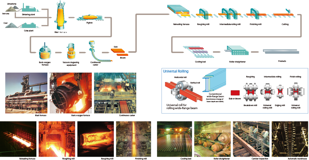
Production Process
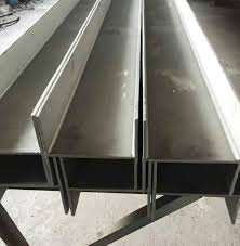
H-Beam and I-Beam: Applications
H-Beams and I-beams are very similar, but they have different applications. If you’re interested in using either of them for your next project, here’s what you need to know:
- The best way to determine which beam is best for your project is to consult a professional. H-beams are better suited to support the load of the floor and roof over longer distances, while i-beams are better suited to support the weight of a wall or column.
- If you do decide on an H-beam or an I-beam, note that these beams have different minimum spans; this means that if your space has a large span (i.e., it’s long), then an I-beam may not be right for it because it requires more material than other designs.
.jpg")